Cisco IOSでMPLSを使用するためには、前提としてVRFを理解しなければなりません。VRFとは Virtual Routing Forwardingの略で、ひとつのルータ内で複数のルーティングテーブルを持つ機能です。それぞれのルーティングテーブルは独立しており、基本的にVRFをまたぐ転送はできません。このページではciscoルータにおけるVRFの設定例について紹介します。基本的な技術説明については、VRF Lite 設定方法を参照下さい。
動作確認環境
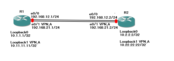
以下の構成で動作確認を行います。

 [R1:cisco3640]
interface Loopback0
 ip address 10.1.1.1 255.255.255.255
!
interface Loopback1
 ip address 10.11.11.11 255.255.255.255
!
interface Ethernet0/0
 ip address 192.168.12.1 255.255.255.0
!
interface Ethernet0/1
 ip address 192.168.21.1 255.255.255.0


 [R2:cisco3640]
interface Loopback0
 ip address 10.2.2.2 255.255.255.255
!
interface Loopback1
 ip address 10.22.22.22 255.255.255.255
!
interface Ethernet0/0
 ip address 192.168.12.2 255.255.255.0
!
interface Ethernet0/1
 ip address 192.168.21.2 255.255.255.0
初期設定の全文は以下を参照下さい。
VRFの定義
VRFの定義 設定投入
R1, R2で、VPN_Aという名前のVRFを定義します。
 [R1:cisco3640]
ip vrf VPN_A
 rd 100:1

 [R2:cisco3640]
ip vrf VPN_A
 rd 100:1
VRFの定義 設定確認
VRFが作成された事を”show ip vrf”コマンドにて作成します。
 [R1:cisco3640]
R1#show ip vrf
  Name                             Default RD          Interfaces
  VPN_A                            100:1
R1#
VRF インターフェースの定義
VRF インターフェースの定義 設定投入
R1, R2のe0/1, Lo1をVPN_Aに所属されます。”ip vrf forwarding”コマンドによってVRFへの所属を定義すると、IPアドレスの再設定が必要になる事に注意して下さい。
 [R1:cisco3640]
interface Ethernet0/1
 ip vrf forwarding VPN_A
 ip address 192.168.21.1 255.255.255.0
!
interface Loopback1
 ip vrf forwarding VPN_A
 ip address 10.11.11.11 255.255.255.255

 [R2:cisco3640]
interface Ethernet0/1
 ip vrf forwarding VPN_A
 ip address 192.168.21.2 255.255.255.0
!
interface Loopback1
 ip vrf forwarding VPN_A
 ip address 10.22.22.22 255.255.255.255
VRF インターフェースの定義 設定確認
“show ip vrf”コマンドにより、どのインターフェースがどのVRFに所属しているかを確認します。
 [R1:cisco3640]
R1#show ip vrf
  Name                             Default RD          Interfaces
  VPN_A                            100:1               Et0/1
                                                       Lo1
R1#
VRF ルーティングの定義
VRF ルーティングの定義 設定投入
グローバルルーティングテーブルについて、以下のようなstatic routeを定義します。
 [R1:cisco3640]
ip route 0.0.0.0 0.0.0.0 192.168.12.2

 [R2:cisco3640]
ip route 0.0.0.0 0.0.0.0 192.168.12.1
VPN_Aという名前のVRFについて、static routeを定義します。
VRFのルーティング定義は、”ip route vrf”コマンドを使用します。
 [R1:cisco3640]
ip route vrf VPN_A 0.0.0.0 0.0.0.0 192.168.21.2

 [R2:cisco3640]
ip route vrf VPN_A 0.0.0.0 0.0.0.0 192.168.21.1
VRF ルーティングの定義 設定確認
“show ip route vrf”コマンドにより、VPN_AというVRFのルーティングテーブルを確認します。先ほど設定したstatic routeを確認して下さい。
 [R1:cisco3640]
R1#show ip route vrf VPN_A

Routing Table: VPN_A
Codes: C - connected, S - static, R - RIP, M - mobile, B - BGP
       D - EIGRP, EX - EIGRP external, O - OSPF, IA - OSPF inter area
       N1 - OSPF NSSA external type 1, N2 - OSPF NSSA external type 2
       E1 - OSPF external type 1, E2 - OSPF external type 2
       i - IS-IS, su - IS-IS summary, L1 - IS-IS level-1, L2 - IS-IS level-2
       ia - IS-IS inter area, * - candidate default, U - per-user static route
       o - ODR, P - periodic downloaded static route

Gateway of last resort is 192.168.21.2 to network 0.0.0.0

C    192.168.21.0/24 is directly connected, Ethernet0/1
     10.0.0.0/32 is subnetted, 1 subnets
C       10.11.11.11 is directly connected, Loopback1
S*   0.0.0.0/0 [1/0] via 192.168.21.2
R1#
疎通確認
グローバルルーティングテーブルの疎通確認
R1からpingによる疎通確認を行います。R1のグローバルルーティングテーブルからのpingなので、R2のグローバルルーティングテーブルへの疎通は可能ですが、R2のVPN_Aへの疎通は不能です。
 [R1:cisco3640]
R1#ping 10.1.1.1

Type escape sequence to abort.
Sending 5, 100-byte ICMP Echos to 10.1.1.1, timeout is 2 seconds:
!!!!!
Success rate is 100 percent (5/5), round-trip min/avg/max = 4/4/4 ms
R1#
R1#
R1#ping 10.11.11.11

Type escape sequence to abort.
Sending 5, 100-byte ICMP Echos to 10.11.11.11, timeout is 2 seconds:
.....
Success rate is 0 percent (0/5)
R1#
VRFの疎通確認
R1からpingによる疎通確認を行います。R1のVPN_Aからのpingなので、R2のVPN_Aへの疎通は可能ですが、R2のグローバルルーティングテーブルへの疎通は不能です。
 [R1:cisco3640]
R1#ping vrf VPN_A 10.11.11.11

Type escape sequence to abort.
Sending 5, 100-byte ICMP Echos to 10.11.11.11, timeout is 2 seconds:
!!!!!
Success rate is 100 percent (5/5), round-trip min/avg/max = 1/4/8 ms
R1#
R1#
R1#
R1#ping vrf VPN_A 10.1.1.1

Type escape sequence to abort.
Sending 5, 100-byte ICMP Echos to 10.1.1.1, timeout is 2 seconds:
.....
Success rate is 0 percent (0/5)
R1#

