
Catalyst 3560にはルータとは異なる独自のQoSが存在します。Catalyst 3560には4つの出力キューが存在し、SRR (Shared Round Robin)という特殊なアルゴリズムによってパケットの割り振りを行います。
コマンド一覧
このシナリオで重要なコマンド一覧は以下の通りです。
Switch(config)# mls qos

Switch(config)# mls qos srr-queue output cos-map queue <id> <cos>...
Switch(config)# mls qos srr-queue output dscp-map queue <id> <dscp>...
Switch(config)# mls qos queue-set output <queue_set_id> buffers <queue1> <queue2> <queue3> <queue4>
Switch(config)# mls qos queue-set output <queue_set_id> threshold <queue_id> <drop_threshold1> <drop_threshold2> <reserved_threshold1> <maximum_threshold1>

Swtich(config)# interface <interface>
Switch(config-if)# srr-queue bandwidth limit <percent>
Switch(config-if)# srr-queue bandwidth share <queue1> <queue2> <queue3> <queue4>
Switch(config-if)# srr-queue bandwidth shape <queue1> <queue2> <queue3> <queue4>
Switch(config-if)# queue-set <queue_set_id>
Switch(config-if)# priority-queue out
構成図
以下の構成で動作確認を行います。
 [physical diagram]
    +------+f0/0    +------+f0/13   +------+f0/1    +------+
    |  R1  +--------+ SW 1 +--------+ SW 2 +--------+  R2  |
    +------+    f0/1+------+   f0/13+------+    f0/0+------+

 [logical diagram]
           192.168.12.0/24
          f0/0        f0/0
    +------+.1        .1+------+
    |      +------------+      |
    |  R1  |            |  R2  |
    |      +------------+      |
    +------+.2        .2+------+
         f0/0.21    f0/0.21
          192.168.21.0/24
 [R1]
ipx routing
!
interface FastEthernet0/0
 ip address 192.168.12.1 255.255.255.0
!
interface FastEthernet0/0.21
 encapsulation dot1Q 21
 ip address 192.168.21.1 255.255.255.0
 ipx network 21 encapsulation SNAP
!
line vty 0 4
 password cisco
 login

 [R2]
ipx routing
!
interface FastEthernet0/0
 ip address 192.168.12.2 255.255.255.0
!
interface FastEthernet0/0.21
 encapsulation dot1Q 21
 ip address 192.168.21.2 255.255.255.0
 ipx network 21 encapsulation SNAP
!
line vty 0 4
 password cisco
 login

 [SW1]
vlan 12,21
!
interface FastEthernet0/1
 switchport trunk encapsulation dot1q
 switchport trunk native vlan 12
 switchport mode trunk
!
interface FastEthernet0/13
 switchport trunk encapsulation dot1q
 switchport mode trunk
!
interface range FastEthernet0/14 - 21
 shutdown

 [SW2]
vlan 12,21
!
interface FastEthernet0/1
 switchport trunk encapsulation dot1q
 switchport trunk native vlan 12
 switchport mode trunk
!
interface FastEthernet0/13
 switchport trunk encapsulation dot1q
 switchport mode trunk
!
interface range FastEthernet0/14 - 21
 shutdown
設定全文は下記ファイルです。詳細設定は下記を参照ください。
仕様説明
mls qos
Catalyst 3560はSRR(Shared Round Robin)という独自キューイング機能を備えております。この機能を有効にするには、mls qosを有効にする必要があります。
Switch(config)# mls qos
SRR share mode
Catalyst 3560には4つのoutput queueが存在します。以下のコマンドでどのCoS値がどのキューに格納されるのかを定義する事ができます。
Switch(config)# mls qos srr-queue output cos-map queue <id> <cos>...
Catalyst 3560 output queueはshare modeとshape modeの2種類の送信方式があります。各モードのパラメータ設定コマンドは以下の通りです。また、”priority-queue out”を指定すると、queue1が絶対優先キューとして取り扱われます。”srr-queue bandwidth limit”はshare modeによる送信量を制限する事ができる設定です。
Switch(config-if)# srr-queue bandwidth share <queue1> <queue2> <queue3> <queue4>
Switch(config-if)# srr-queue bandwidth shape <queue1> <queue2> <queue3> <queue4>
Switch(config-if)# priority-queue out
Switch(config-if)# srr-queue bandwidth limit <percent>
share modeの設定例は以下の通りです。queue1が絶対優先キューとして取り扱われ、それ以外のキューが1:2:3の割合で送信されます。また、送信可能な帯域はsrr-queue bandwidth limitコマンドにより2Mbpsに制限されています。なお、share modeを使用したい場合は、shape modeのパラメタを0 0 0 0と指定して下さい。
interface FastEthernet0/1
 speed 10
 srr-queue bandwidth share 1 10 20 30
 srr-queue bandwidth shape  0  0  0  0
 srr-queue bandwidth limit 20
SRR shape mode
shape modeの設定コマンドは以下の通りです。各キューに対するweightを定義します。各キューの送信権はspeed / weightにより算出されます。
Switch(config-if)# srr-queue bandwidth shape <queue1> <queue2> <queue3> <queue4>
shape modeの設定例は以下の通りです。queue1, queue2がshape modeにより10Mbps, 5Mbpsの帯域が割り当てられます。share modeにより、残りの85Mbpsをqueue3, queue4のそれぞれ25.5Mbps, 59.5Mbpsずつ分配します。
interface FastEthernet0/1
 speed 100
 srr-queue bandwidth share 1 1 30 70
 srr-queue bandwidth shape 10 20 0 0
計算式は以下の通りです。
queue1 : 100Mbps / 10 = 10Mbps
queue2 : 100Mbps / 20 = 5Mbps
queue3 : (100Mbps - 10Mbps - 5Mbps) * 30 / ( 30 + 70 ) = 25.5Mbps
queue4 : (100Mbps - 10Mbps - 5Mbps) * 70 / ( 30 + 70 ) = 59.5Mbps
threshold
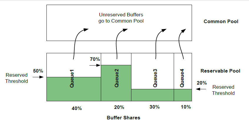
SRR output queueはReserved Pool, Common Poolという2つのメモリ領域が存在します。mls qos queue-set output <queue_set_id> buffersにより各queueのサイズを指定し、mls qos queue-set output <queue_set_id> thresholdの<reserved_threshold1>パラメタによりReserved Poolの割合を指定します。
Switch(config)# mls qos queue-set output <queue_set_id> buffers <queue1> <queue2> <queue3> <queue4>
Switch(config)# mls qos queue-set output <queue_set_id> threshold <queue_id> <drop_threshold1> <drop_threshold2> <reserved_threshold1> <maximum_threshold1>
以下の例について考察します。queue1, 2, 3, 4にそれぞれ2:4:3:1の割合でメモリを割り当てます。queue1, 2, 3, 4のそれぞれについて、50%. 70%, 20%, 20%をReserved Poolとして扱い残りをCommon Poolとして扱います。
mls qos queue-set output 2 buffers 20 40 30 10
mls qos queue-set output 2 threshold 1 100 100 50 250
mls qos queue-set output 2 threshold 2 100 100 70 250
mls qos queue-set output 2 threshold 3 100 100 20 250
mls qos queue-set output 2 threshold 4 100 100 20 250
図示すると以下の通りです。
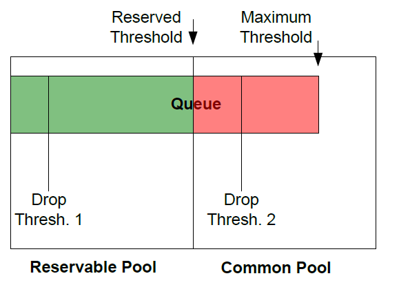
以下のコマンドで、<drop_threshold1> <drop_threshold2> <maximum_threshold1>の3種類のthresholdを定義する事ができます。Reserved poolを超えた場合はCommon Poolに格納されるので、100%よりも大きい閾値を定義する事ができます。
Switch(config)# mls qos queue-set output <queue_set_id> threshold <queue_id> <drop_threshold1> <drop_threshold2> <reserved_threshold1> <maximum_threshold1>
設定例は以下の通りです。
threshold1, threshold2, maximun_thresholdを20, 100, 130とする設定例です。
mls qos queue-set output 2 threshold 1 20 100 80 130
図示すると以下の通りです。
threshold1, threshold2, maximun_threshold等の設定は、2種類までしか定義する事ができません。定義した設定は<queue_set_id>というパラメタを用いて設定します。設定コマンドは以下の通りです。
Switch(config-if)# queue-set <queue_set_id>
SRR share mode
設定投入
以下の設定をSW1に投入し、SRR share modeによるキューイングを行います。
 [SW1]
mls qos srr-queue output cos-map queue 1 5
mls qos srr-queue output cos-map queue 2 0 1
mls qos srr-queue output cos-map queue 3 2 3
mls qos srr-queue output cos-map queue 4 4 6 7
!
interface FastEthernet0/1
 speed 10
 srr-queue bandwidth share 1 10 20 30
 srr-queue bandwidth shape  0  0  0  0
 srr-queue bandwidth limit 20
 priority-queue out
設定確認
show runにより設定を確認します。なお、デフォルト設定と変わらないコマンドはshow runで表示されません。
 [SW1]
SW1#show running-config | include ^mls
mls qos
SW1#
cosとqueue割り当ての関係は以下のコマンドで確認できます。
 [SW1]
SW1#show mls qos maps cos-output-q
   Cos-outputq-threshold map:
              cos:  0   1   2   3   4   5   6   7
              ------------------------------------
  queue-threshold: 2-1 2-1 3-1 3-1 4-1 1-1 4-1 4-1


SW1#
SRR output queueの設定は以下コマンドにより確認できます。
 [SW1]
SW1#show mls qos interface FastEthernet 0/1 queueing
FastEthernet0/1
Egress Priority Queue : enabled
Shaped queue weights (absolute) :  0 0 0 0
Shared queue weights  :  1 10 20 30
The port bandwidth limit : 20  (Operational Bandwidth:20.0)
The port is mapped to qset : 1

SW1#
SRR shape mode
設定投入
以下の設定をSW1に投入し、SRR shape modeによるキューイングを行います。
 [SW1]
interface FastEthernet0/1
 speed 10
 srr-queue bandwidth limit 20
 srr-queue bandwidth share 0 0 30 70
 srr-queue bandwidth shape 10 20 0 0
 no priority-queue out
設定確認
確認コマンドは以下の通りです。
 [SW1]
SW1#show mls qos interface FastEthernet 0/1 queueing
FastEthernet0/1
Egress Priority Queue : disabled
Shaped queue weights (absolute) :  10 20 0 0
Shared queue weights  :  0 0 30 70
The port bandwidth limit : 20  (Operational Bandwidth:20.0)
The port is mapped to qset : 1

SW1#
SRR shape mode
設定投入
以下の設定をSW1に投入し、threshold, bufferをチューニングします。
 [SW1]
ls qos srr-queue output dscp-map threshold 3 46
mls qos srr-queue output dscp-map threshold 2 8 10 18 34
mls qos queue-set output 2 threshold 1 200 150 100 250
mls qos queue-set output 2 threshold 2 200 150 10 250
mls qos queue-set output 2 threshold 3 200 150 100 250
mls qos queue-set output 2 threshold 4 200 150 100 250
mls qos queue-set output 2 buffers 10 70 10 10
!
interface FastEthernet0/1
 queue-set 2
 mls qos trust dscp
設定確認
確認コマンドは以下の通りです。
 [SW1]
SW1#show running-config | i ^mls
mls qos srr-queue output dscp-map queue 1 threshold 3  46
mls qos srr-queue output dscp-map queue 2 threshold 2  8 10
mls qos srr-queue output dscp-map queue 3 threshold 2  18
mls qos srr-queue output dscp-map queue 4 threshold 2  34
mls qos queue-set output 2 threshold 1 200 150 100 250
mls qos queue-set output 2 threshold 2 200 150 10 250
mls qos queue-set output 2 threshold 3 200 150 100 250
mls qos queue-set output 2 threshold 4 200 150 100 250
mls qos queue-set output 2 buffers 10 70 10 10
mls qos
SW1#
SW1#
SW1#
SW1#show mls qos maps dscp-output-q
   Dscp-outputq-threshold map:
     d1 :d2    0     1     2     3     4     5     6     7     8     9
     ------------------------------------------------------------
      0 :    02-01 02-01 02-01 02-01 02-01 02-01 02-01 02-01 02-02 02-01
      1 :    02-02 02-01 02-01 02-01 02-01 02-01 03-01 03-01 03-02 03-01
      2 :    03-01 03-01 03-01 03-01 03-01 03-01 03-01 03-01 03-01 03-01
      3 :    03-01 03-01 04-01 04-01 04-02 04-01 04-01 04-01 04-01 04-01
      4 :    01-01 01-01 01-01 01-01 01-01 01-01 01-03 01-01 04-01 04-01
      5 :    04-01 04-01 04-01 04-01 04-01 04-01 04-01 04-01 04-01 04-01
      6 :    04-01 04-01 04-01 04-01


SW1#
SW1#
SW1#
SW1#show mls qos interface FastEthernet 0/1 queueing
FastEthernet0/1
Egress Priority Queue : disabled
Shaped queue weights (absolute) :  0 0 30 70
Shared queue weights  :  1 10 20 30
The port bandwidth limit : 20  (Operational Bandwidth:20.0)
The port is mapped to qset : 2

SW1#
SW1#
SW1#
SW1#show mls qos queue-set 2
Queueset: 2
Queue     :       1       2       3       4
----------------------------------------------
buffers   :      10      70      10      10
threshold1:     200     200     200     200
threshold2:     150     150     150     150
reserved  :     100      10     100     100
maximum   :     250     250     250     250
SW1#
SW1#
SW1#
SW1#show mls qos interface FastEthernet 0/1 buffers
FastEthernet0/1
The port is mapped to qset : 2
The allocations between the queues are : 10 70 10 10

SW1#