NSX-Tの負荷分散構成について考察します。このページではヴイエムウェア社が非推奨としているmLAGを使用したNSX-T Edgeアップリンクの冗長構成について説明します。mLAGを使用するためには一定価格帯以上のネットワーク機器を購入する必要があるものの、mLAGを使用することでNSX-Tの設定を非常に簡単にすることができます。
「Physical Network Design Decisions」によると、「No EtherChannel (LAG/vPC) configuration for ESXi host uplinks」と書かれています。
構成図
「NSX-T アップリンクの負荷分散(mLAGあり)」「NSX-T オーバーレイの負荷分散(mLAGあり)」の併せて2記事で以下のような構成を組み上げます。mLAGなしの場合と比較すると、かなり単純な構成です。
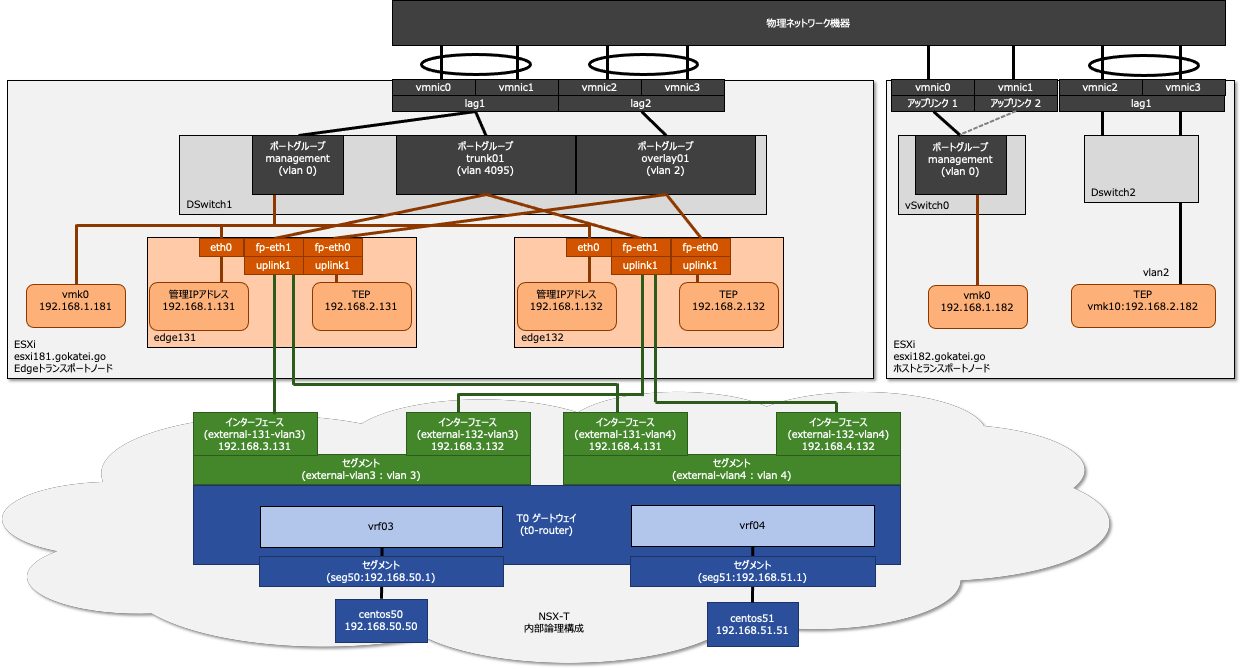
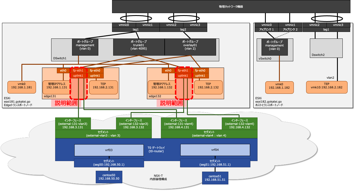
このページでは赤枠で囲まれた部分のNSX Edgeのアップリンクの負荷分散構成を説明します。
前提条件
LAG(LACP)
負荷分散と冗長化を実現のmLAGは設定済の状態で説明します。ESXi側のLAG設定は「分散仮想スイッチ(VDS)の冗長化設定とロードバランシングアルゴリズムまとめ」を参照ください。
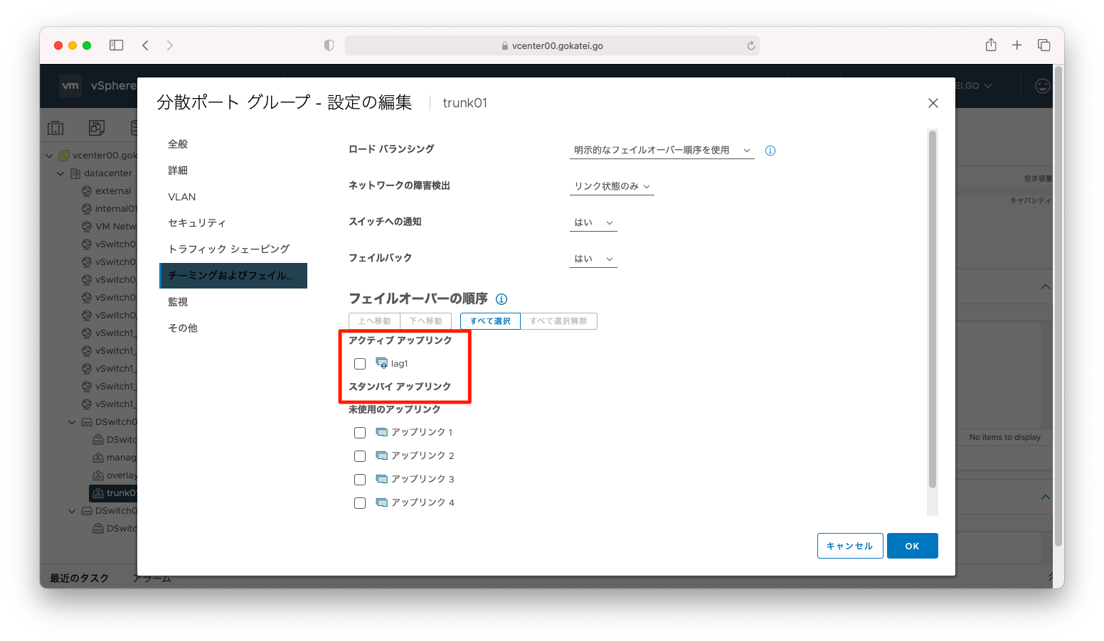
ポートグループtrunk01のアップリンクにLAG(LACP)を指定します。
物理ネットワーク機器側の操作でLACPによるチャネルが形成されていることを確認します。
Switch#show etherchannel summary
Flags:  D - down        P - bundled in port-channel
        I - stand-alone s - suspended
        H - Hot-standby (LACP only)
        R - Layer3      S - Layer2
        U - in use      f - failed to allocate aggregator

        M - not in use, minimum links not met
        u - unsuitable for bundling
        w - waiting to be aggregated
        d - default port


Number of channel-groups in use: 3
Number of aggregators:           3

Group  Port-channel  Protocol    Ports
------+-------------+-----------+-----------------------------------------------
1      Po1(SU)         LACP      Fa0/1(P)    Fa0/2(P)
2      Po2(SU)         LACP      Fa0/3(P)    Fa0/4(P)
4      Po4(SU)         LACP      Fa0/7(P)    Fa0/8(P)
ロードバランシングアルゴリズム
ネットワーク機器によっては、デフォルト設定が送信元MACアドレスなどの十分負荷分散されないロードバランシングアルゴリズムになっていることもあります。
Switch#show etherchannel load-balance
EtherChannel Load-Balancing Configuration:
        src-mac

EtherChannel Load-Balancing Addresses Used Per-Protocol:
Non-IP: Source MAC address
  IPv4: Source MAC address
  IPv6: Source MAC address
このような場合はロードバランスされるアルゴリズムに変更します。
Switch(config)#port-channel load-balance src-dst-ip
Switch(config)#exit
Switch#show etherchannel load-balance
EtherChannel Load-Balancing Configuration:
        src-dst-ip

EtherChannel Load-Balancing Addresses Used Per-Protocol:
Non-IP: Source XOR Destination MAC address
  IPv4: Source XOR Destination IP address
  IPv6: Source XOR Destination IP address

Switch#
システム設定
アップリンクプロファイル
アップリンクプロファイルは、アップリンクが1つのみの設定を作成します。冗長化および負荷分散はVDS(分散仮想スイッチ)のLACPによって実現されるため、NSX-T側の設定は非常に単純になります。
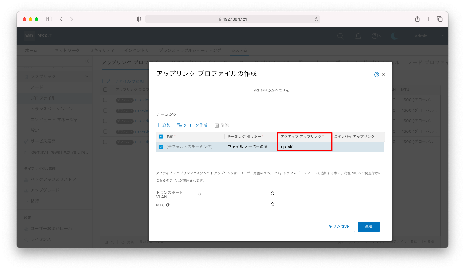
アップリンクプロファイルの設定全文は以下の通りです。
アップリンクプロファイル
administrator@ubuntu106:~$ curl --silent --request GET \
>   -u admin:P@ssw0rdP@ssw0rd \
>   --header "Content-Type:application/json" \
>   -k https://192.168.1.121/api/v1/host-switch-profiles \
>   | jq ' .results[] | select ( .display_name == "prof-edge-single-vlan-4095" ) '
{
  "teaming": {
    "policy": "FAILOVER_ORDER",
    "active_list": [
      {
        "uplink_name": "uplink1",
        "uplink_type": "PNIC"
      }
    ]
  },
  "named_teamings": [],
  "transport_vlan": 0,
  "overlay_encap": "GENEVE",
  "resource_type": "UplinkHostSwitchProfile",
  "id": "c8abbf8b-9796-4e3f-bab4-08e51bf7526c",
  "display_name": "prof-edge-single-vlan-4095",
  "description": "",
  "tags": [],
  "_create_user": "admin",
  "_create_time": 1620823421070,
  "_last_modified_user": "admin",
  "_last_modified_time": 1620823421070,
  "_system_owned": false,
  "_protection": "NOT_PROTECTED",
  "_revision": 0
}
VLANトランスポートゾーン
VLANトランスポートゾーンの設定は以下の通りです。非常に単純で「NSX-T アップリンクの負荷分散(mLAGなし)」で説明したようなチーミングポリシーの設定は不要です。冗長化および負荷分散はVDS(分散仮想スイッチ)のLACPによって実現されます。
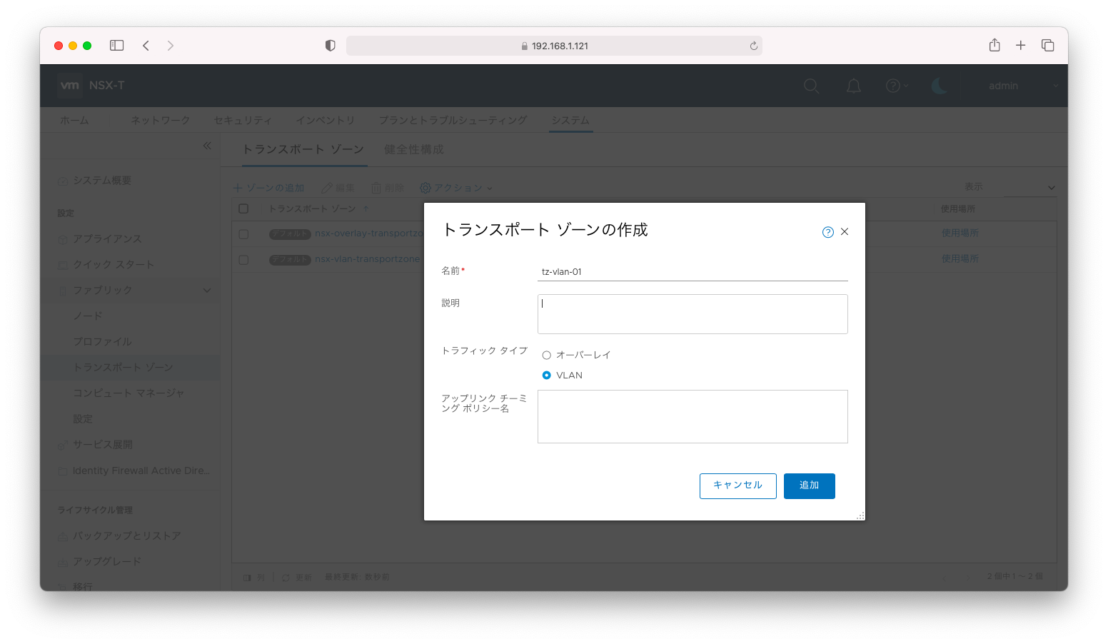
トランスポートゾーンの設定全文は以下の通りです。
トランスポートゾーン
administrator@ubuntu106:~$ curl --silent --request GET \
>   -u admin:P@ssw0rdP@ssw0rd \
>   --header "Content-Type:application/json" \
>   -k https://192.168.1.121/api/v1/transport-zones \
>   | jq ' .results[] | select ( .display_name == "tz-vlan-01" ) '
{
  "transport_type": "VLAN",
  "host_switch_name": "nsxDefaultHostSwitch",
  "host_switch_id": "70e7e8b1-78c6-4ee0-adba-3382bac3a264",
  "transport_zone_profile_ids": [
    {
      "resource_type": "BfdHealthMonitoringProfile",
      "profile_id": "52035bb3-ab02-4a08-9884-18631312e50a"
    }
  ],
  "host_switch_mode": "STANDARD",
  "nested_nsx": false,
  "is_default": false,
  "resource_type": "TransportZone",
  "id": "f1fffe2f-9d35-4ee1-952a-31dab7cbaf10",
  "display_name": "tz-vlan-01",
  "_create_user": "admin",
  "_create_time": 1620824657859,
  "_last_modified_user": "admin",
  "_last_modified_time": 1620824657859,
  "_system_owned": false,
  "_protection": "NOT_PROTECTED",
  "_revision": 0,
  "_schema": "/v1/schema/TransportZone"
}
ノードスイッチの設定
NSX Edgeに対してノードスイッチを設定します。
さきほどの操作で作成したアップリンクプロファイルとVLANトランスポートゾーンを適用します。
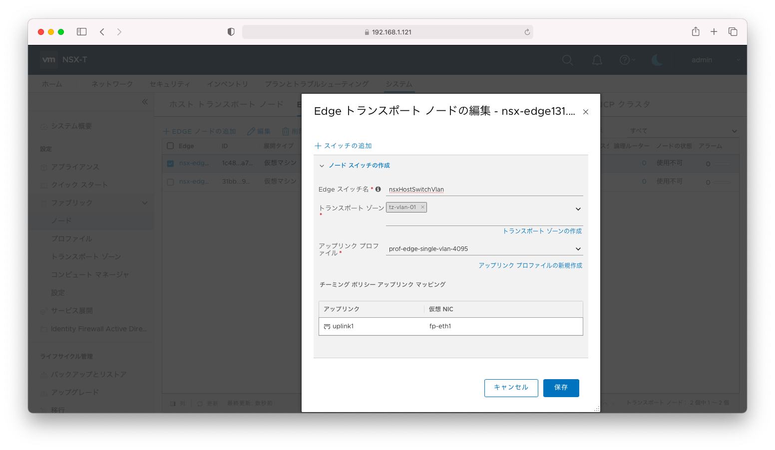
ノードスイッチの設定全文は以下の通りです。
ESXi ノードスイッチ
administrator@ubuntu106:~$ curl --silent --request GET \
>   -u admin:P@ssw0rdP@ssw0rd \
>   --header "Content-Type:application/json" \
>   -k https://192.168.1.121/api/v1/transport-nodes \
>   | jq ' .results[] | select ( .display_name == "nsx-edge132.gokatei.go" ) '
{
  "node_id": "31bb2aae-b2d6-11eb-a994-005056b39749",
  "host_switch_spec": {
    "host_switches": [
      {
        "host_switch_name": "nsxHostSwitchVlan",
        "host_switch_id": "4630b8f0-547f-4888-8246-8a63c4e40c7f",
        "host_switch_type": "NVDS",
        "host_switch_mode": "STANDARD",
        "host_switch_profile_ids": [
          {
            "key": "UplinkHostSwitchProfile",
            "value": "c8abbf8b-9796-4e3f-bab4-08e51bf7526c"
          },
          {
            "key": "LldpHostSwitchProfile",
            "value": "9e0b4d2d-d155-4b4b-8947-fbfe5b79f7cb"
          }
        ],
        "pnics": [
          {
            "device_name": "fp-eth1",
            "uplink_name": "uplink1"
          }
        ],
        "is_migrate_pnics": false,
        "ip_assignment_spec": {
          "resource_type": "AssignedByDhcp"
        },
        "cpu_config": [],
        "transport_zone_endpoints": [
          {
            "transport_zone_id": "f1fffe2f-9d35-4ee1-952a-31dab7cbaf10",
            "transport_zone_profile_ids": [
              {
                "resource_type": "BfdHealthMonitoringProfile",
                "profile_id": "52035bb3-ab02-4a08-9884-18631312e50a"
              }
            ]
          }
        ],
        "vmk_install_migration": [],
        "pnics_uninstall_migration": [],
        "vmk_uninstall_migration": [],
        "not_ready": false
      }
    ],
    "resource_type": "StandardHostSwitchSpec"
  },
  "transport_zone_endpoints": [],
  "maintenance_mode": "DISABLED",
  "node_deployment_info": {
    "deployment_type": "VIRTUAL_MACHINE",
    "node_settings": {
      "hostname": "nsx-edge132.gokatei.go",
      "search_domains": [
        "gokatei.go"
      ],
      "ntp_servers": [
        "192.168.1.221"
      ],
      "dns_servers": [
        "192.168.1.221",
        "192.168.1.1"
      ],
      "enable_ssh": true,
      "allow_ssh_root_login": false
    },
    "resource_type": "EdgeNode",
    "id": "31bb2aae-b2d6-11eb-a994-005056b39749",
    "display_name": "nsx-edge132.gokatei.go",
    "description": "",
    "external_id": "31bb2aae-b2d6-11eb-a994-005056b39749",
    "ip_addresses": [
      "192.168.1.132"
    ],
    "_create_user": "admin",
    "_create_time": 1620821865158,
    "_last_modified_user": "admin",
    "_last_modified_time": 1620824938636,
    "_system_owned": false,
    "_protection": "NOT_PROTECTED",
    "_revision": 1
  },
  "is_overridden": false,
  "failure_domain_id": "4fc1e3b0-1cd4-4339-86c8-f76baddbaafb",
  "resource_type": "TransportNode",
  "id": "31bb2aae-b2d6-11eb-a994-005056b39749",
  "display_name": "nsx-edge132.gokatei.go",
  "description": "",
  "tags": [],
  "_create_user": "admin",
  "_create_time": 1620821865205,
  "_last_modified_user": "admin",
  "_last_modified_time": 1620824938655,
  "_system_owned": false,
  "_protection": "NOT_PROTECTED",
  "_revision": 1
}
Edgeクラスタ
以上の操作で作成されたNSX Edgeに対してクラスタを作成します。
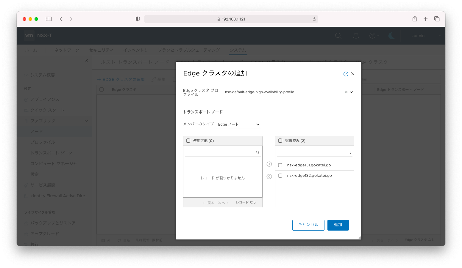
Edgeクラスタの設定全文は以下の通りです。
Edgeクラスタ
administrator@ubuntu106:~$ curl --silent --request GET \
>   -u admin:P@ssw0rdP@ssw0rd \
>   --header "Content-Type:application/json" \
>   -k https://192.168.1.121/api/v1/edge-clusters
{
  "results" : [ {
    "deployment_type" : "VIRTUAL_MACHINE",
    "members" : [ {
      "member_index" : 0,
      "transport_node_id" : "1c485f98-b2d6-11eb-9437-005056b3a7a9"
    }, {
      "member_index" : 1,
      "transport_node_id" : "31bb2aae-b2d6-11eb-a994-005056b39749"
    } ],
    "cluster_profile_bindings" : [ {
      "resource_type" : "EdgeHighAvailabilityProfile",
      "profile_id" : "91bcaa06-47a1-11e4-8316-17ffc770799b"
    } ],
    "member_node_type" : "EDGE_NODE",
    "allocation_rules" : [ ],
    "enable_inter_site_forwarding" : false,
    "resource_type" : "EdgeCluster",
    "id" : "ab4c625e-eb65-4e67-aa50-36c0c6e46477",
    "display_name" : "cluster01",
    "description" : "",
    "tags" : [ ],
    "_create_user" : "admin",
    "_create_time" : 1620825005956,
    "_last_modified_user" : "admin",
    "_last_modified_time" : 1620825005956,
    "_system_owned" : false,
    "_protection" : "NOT_PROTECTED",
    "_revision" : 0
  } ],
  "result_count" : 1
}
ネットワーク設定
外部セグメント
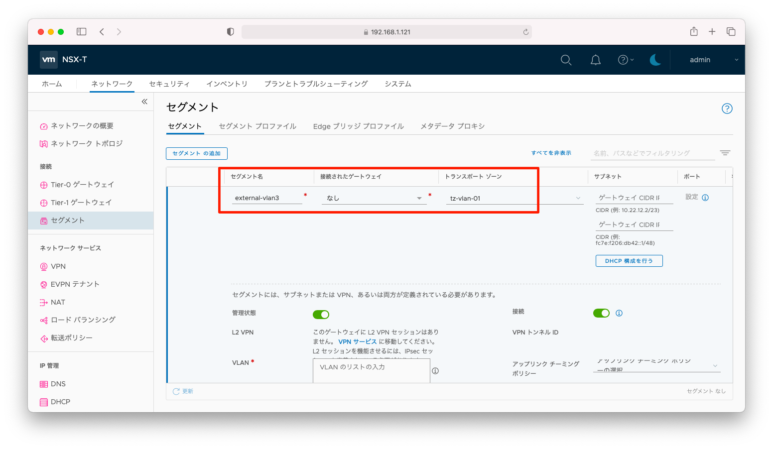
「ネットワーク」「セグメント」「セグメント」の順に押下して表示されるセグメント一覧の画面で、「セグメントの追加」を押下します。
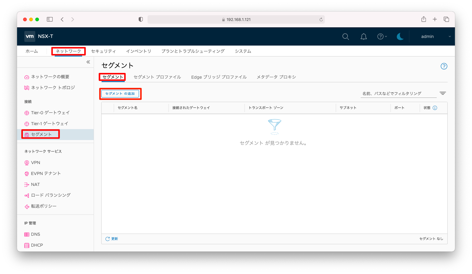
「セグメント名」や「トランスポートゾーン」を入力します。
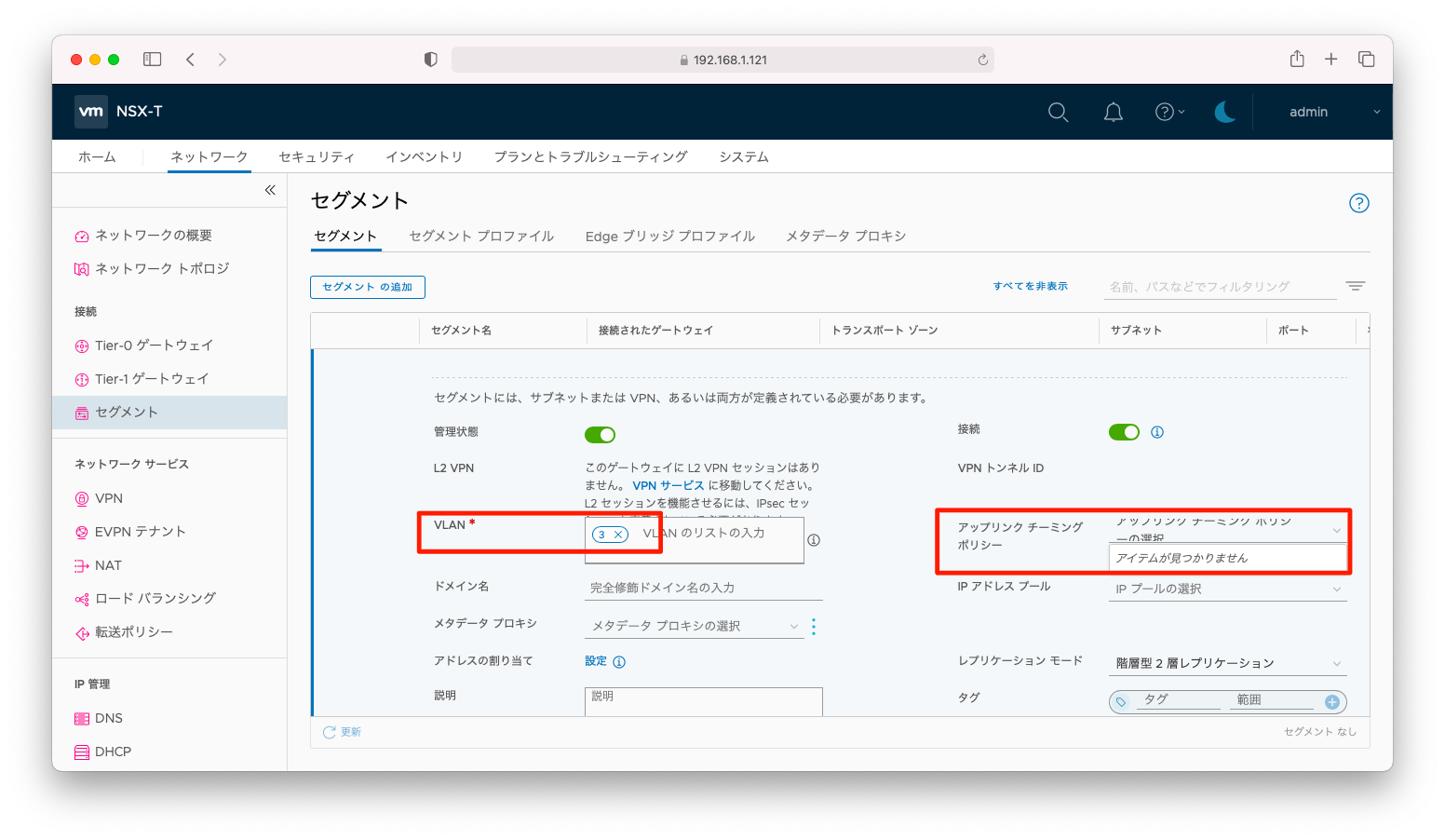
「VLAN ID」を入力します。「NSX-T アップリンクの負荷分散(mLAGなし)」で説明した「アップリンクチーミングポリシー」の設定は不要です。冗長化および負荷分散はVDS(分散仮想スイッチ)のLACPによって実現されます。
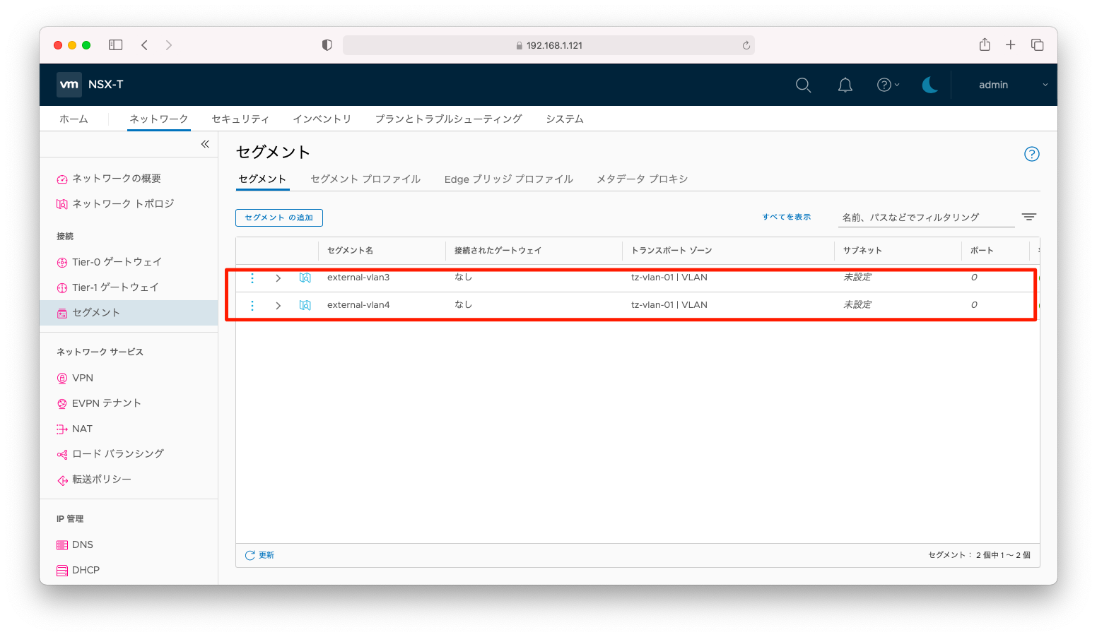
同様の設定を繰り替えし、「external-vlan3」「external-vlan4」の2つのセグメントを作成します。
セグメントの設定全文は以下の通りです。
セグメント
administrator@ubuntu106:~$ curl --silent --request GET \
>   -u admin:P@ssw0rdP@ssw0rd \
>   --header "Content-Type:application/json" \
>   -k https://192.168.1.121/policy/api/v1/infra/segments
{
  "results" : [ {
    "type" : "DISCONNECTED",
    "vlan_ids" : [ "3" ],
    "transport_zone_path" : "/infra/sites/default/enforcement-points/default/transport-zones/f1fffe2f-9d35-4ee1-952a-31dab7cbaf10",
    "advanced_config" : {
      "address_pool_paths" : [ ],
      "hybrid" : false,
      "inter_router" : false,
      "local_egress" : false,
      "urpf_mode" : "STRICT",
      "connectivity" : "ON"
    },
    "admin_state" : "UP",
    "replication_mode" : "MTEP",
    "resource_type" : "Segment",
    "id" : "external-vlan3",
    "display_name" : "external-vlan3",
    "path" : "/infra/segments/external-vlan3",
    "relative_path" : "external-vlan3",
    "parent_path" : "/infra",
    "unique_id" : "d742fcfe-ca8f-4be1-8879-a79759612d26",
    "marked_for_delete" : false,
    "overridden" : false,
    "_create_user" : "admin",
    "_create_time" : 1620825394623,
    "_last_modified_user" : "admin",
    "_last_modified_time" : 1620825394626,
    "_system_owned" : false,
    "_protection" : "NOT_PROTECTED",
    "_revision" : 0
  }, {
    "type" : "DISCONNECTED",
    "vlan_ids" : [ "4" ],
    "transport_zone_path" : "/infra/sites/default/enforcement-points/default/transport-zones/f1fffe2f-9d35-4ee1-952a-31dab7cbaf10",
    "advanced_config" : {
      "address_pool_paths" : [ ],
      "hybrid" : false,
      "inter_router" : false,
      "local_egress" : false,
      "urpf_mode" : "STRICT",
      "connectivity" : "ON"
    },
    "admin_state" : "UP",
    "replication_mode" : "MTEP",
    "resource_type" : "Segment",
    "id" : "external-vlan4",
    "display_name" : "external-vlan4",
    "path" : "/infra/segments/external-vlan4",
    "relative_path" : "external-vlan4",
    "parent_path" : "/infra",
    "unique_id" : "82a26a6b-2307-4081-901d-2e46c5c56703",
    "marked_for_delete" : false,
    "overridden" : false,
    "_create_user" : "admin",
    "_create_time" : 1620825423313,
    "_last_modified_user" : "admin",
    "_last_modified_time" : 1620825423315,
    "_system_owned" : false,
    "_protection" : "NOT_PROTECTED",
    "_revision" : 0
  } ],
  "result_count" : 2,
  "sort_by" : "display_name",
  "sort_ascending" : true
}
T0ゲートウェイ
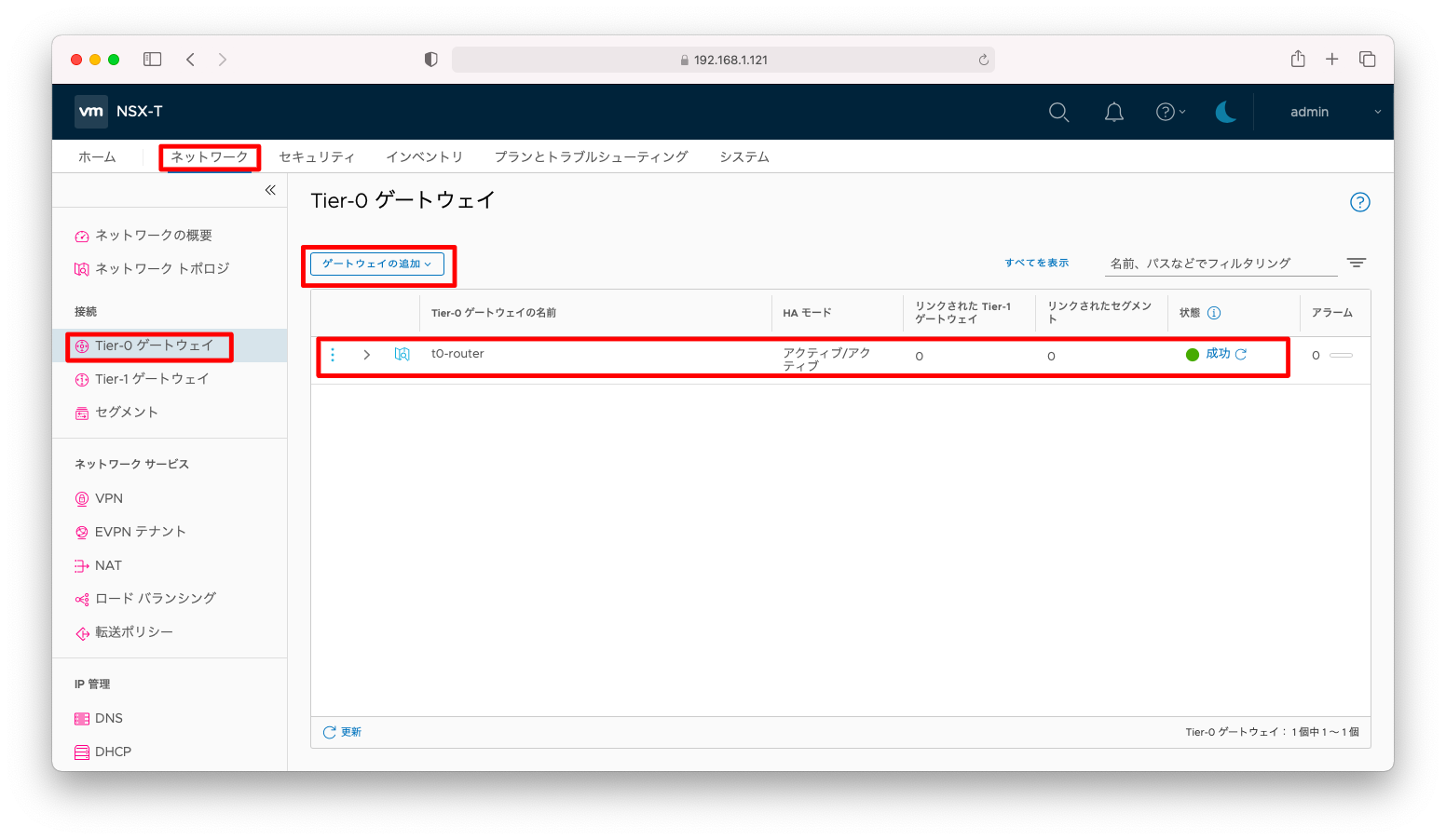
T0ゲートウェイとループバックインターフェースを作成します。設定方法の詳細は「NSX-T VRFの作成」を参照ください。
まず、以下スクリーンショットのようにT0ゲートウェイを作成します。
次に、BGPのルータIDとなるループバックアドレスを定義します。
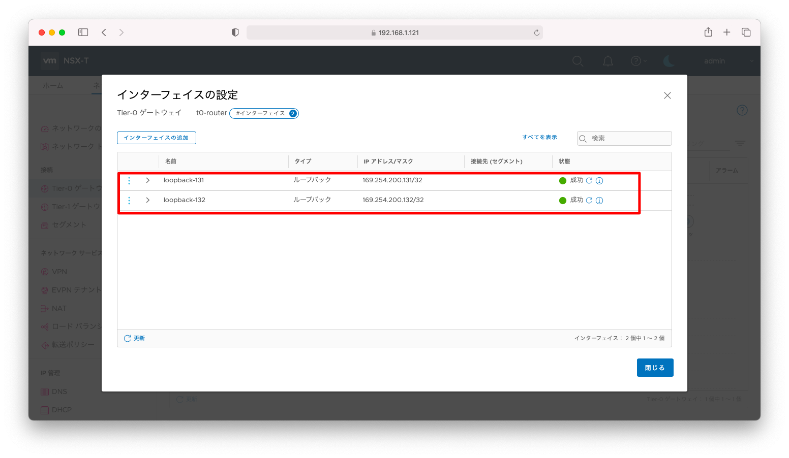
T0ゲートウェイの設定全文は以下の通りです。
T0ゲートウェイ
administrator@ubuntu106:~$ curl --silent --request GET \
>   -u admin:P@ssw0rdP@ssw0rd \
>   --header "Content-Type:application/json" \
>   -k https://192.168.1.121/policy/api/v1/infra/tier-0s/t0-router
{
  "transit_subnets" : [ "100.64.0.0/16" ],
  "internal_transit_subnets" : [ "169.254.0.0/24" ],
  "ha_mode" : "ACTIVE_ACTIVE",
  "failover_mode" : "NON_PREEMPTIVE",
  "ipv6_profile_paths" : [ "/infra/ipv6-ndra-profiles/default", "/infra/ipv6-dad-profiles/default" ],
  "force_whitelisting" : false,
  "default_rule_logging" : false,
  "disable_firewall" : false,
  "advanced_config" : {
    "forwarding_up_timer" : 0,
    "connectivity" : "ON"
  },
  "resource_type" : "Tier0",
  "id" : "t0-router",
  "display_name" : "t0-router",
  "path" : "/infra/tier-0s/t0-router",
  "relative_path" : "t0-router",
  "parent_path" : "/infra",
  "unique_id" : "038117a6-103a-4fdc-b90d-11d80175452e",
  "marked_for_delete" : false,
  "overridden" : false,
  "_create_user" : "admin",
  "_create_time" : 1620826115996,
  "_last_modified_user" : "admin",
  "_last_modified_time" : 1620826116045,
  "_system_owned" : false,
  "_protection" : "NOT_PROTECTED",
  "_revision" : 0
}
インターフェースの設定全文は以下の通りです。
インターフェース
administrator@ubuntu106:~$ curl --silent --request GET \
>   -u admin:P@ssw0rdP@ssw0rd \
>   --header "Content-Type:application/json" \
>   -k https://192.168.1.121/policy/api/v1/infra/tier-0s/t0-router/locale-services/default/interfaces
{
  "results" : [ {
    "urpf_mode" : "STRICT",
    "edge_path" : "/infra/sites/default/enforcement-points/default/edge-clusters/ab4c625e-eb65-4e67-aa50-36c0c6e46477/edge-nodes/0",
    "type" : "LOOPBACK",
    "resource_type" : "Tier0Interface",
    "id" : "loopback-131",
    "display_name" : "loopback-131",
    "path" : "/infra/tier-0s/t0-router/locale-services/default/interfaces/loopback-131",
    "relative_path" : "loopback-131",
    "parent_path" : "/infra/tier-0s/t0-router/locale-services/default",
    "unique_id" : "d4883cb5-84a9-4d95-aecd-8583e12dfcae",
    "marked_for_delete" : false,
    "overridden" : false,
    "subnets" : [ {
      "ip_addresses" : [ "169.254.200.131" ],
      "prefix_len" : 32
    } ],
    "_create_user" : "admin",
    "_create_time" : 1620826157605,
    "_last_modified_user" : "admin",
    "_last_modified_time" : 1620826157610,
    "_system_owned" : false,
    "_protection" : "NOT_PROTECTED",
    "_revision" : 0
  }, {
    "urpf_mode" : "STRICT",
    "edge_path" : "/infra/sites/default/enforcement-points/default/edge-clusters/ab4c625e-eb65-4e67-aa50-36c0c6e46477/edge-nodes/1",
    "type" : "LOOPBACK",
    "resource_type" : "Tier0Interface",
    "id" : "loopback-132",
    "display_name" : "loopback-132",
    "path" : "/infra/tier-0s/t0-router/locale-services/default/interfaces/loopback-132",
    "relative_path" : "loopback-132",
    "parent_path" : "/infra/tier-0s/t0-router/locale-services/default",
    "unique_id" : "e7fd8123-180a-4655-9918-beb7488a9874",
    "marked_for_delete" : false,
    "overridden" : false,
    "subnets" : [ {
      "ip_addresses" : [ "169.254.200.132" ],
      "prefix_len" : 32
    } ],
    "_create_user" : "admin",
    "_create_time" : 1620826177950,
    "_last_modified_user" : "admin",
    "_last_modified_time" : 1620826177966,
    "_system_owned" : false,
    "_protection" : "NOT_PROTECTED",
    "_revision" : 0
  } ],
  "result_count" : 2,
  "sort_by" : "display_name",
  "sort_ascending" : true
}
VRF
VRFと外部インターフェースを作成します。設定方法の詳細は「NSX-T VRFの作成」を参照ください。
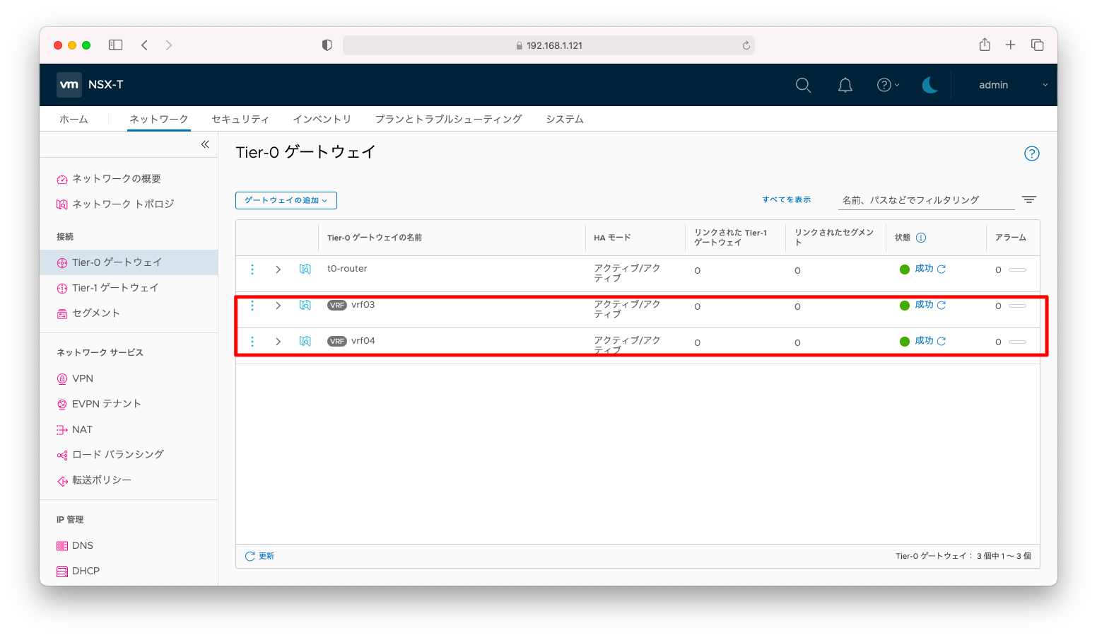
まず、以下スクリーンショットのようにVRFを作成します。
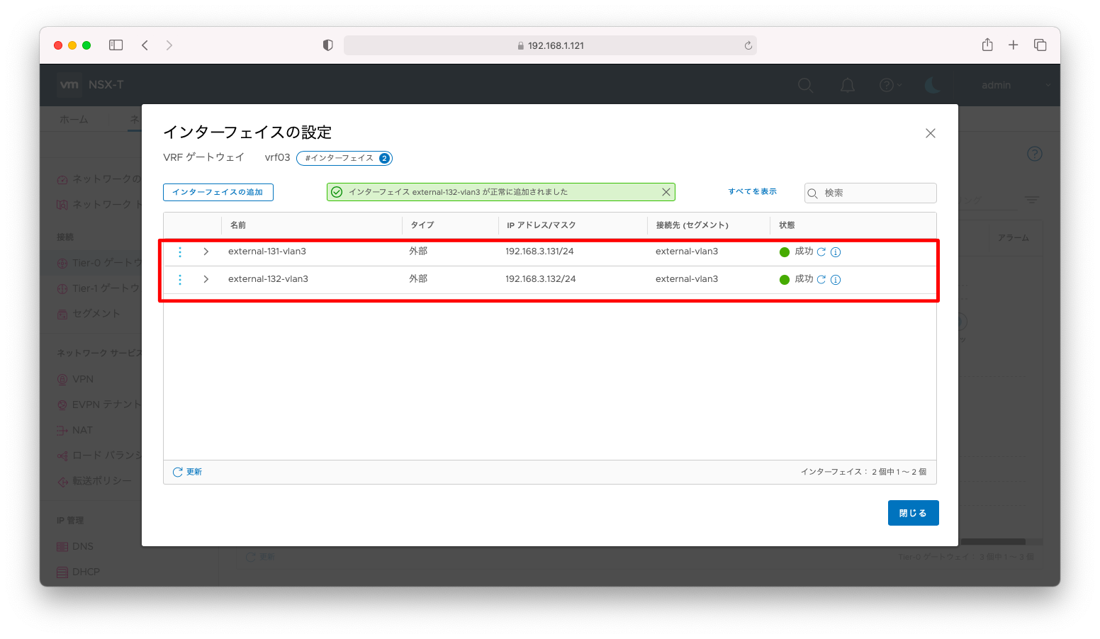
vrf03にvlan3に所属するインターフェースを作成します。
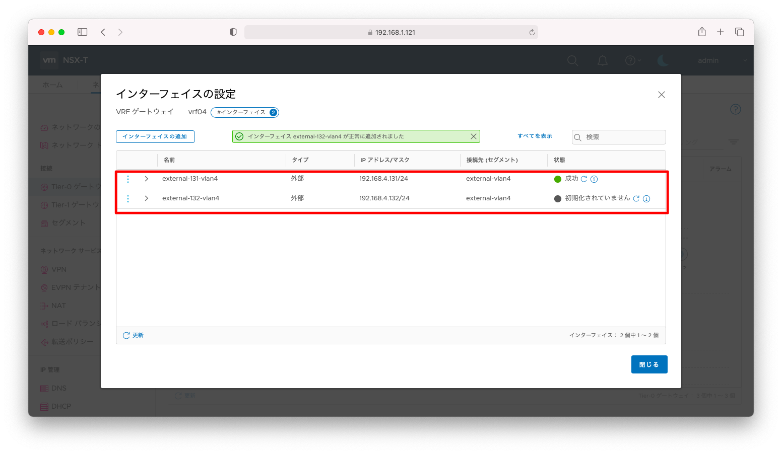
vrf04にvlan4に所属するインターフェースを作成します。
VRFの設定全文は以下の通りです。
VRF
administrator@ubuntu106:~$ curl --silent --request GET \
>   -u admin:P@ssw0rdP@ssw0rd \
>   --header "Content-Type:application/json" \
>   -k https://192.168.1.121/policy/api/v1/infra/tier-0s/vrf03
{
  "transit_subnets" : [ "100.64.0.0/16" ],
  "internal_transit_subnets" : [ "169.254.0.0/24" ],
  "ha_mode" : "ACTIVE_ACTIVE",
  "failover_mode" : "NON_PREEMPTIVE",
  "ipv6_profile_paths" : [ "/infra/ipv6-ndra-profiles/default", "/infra/ipv6-dad-profiles/default" ],
  "force_whitelisting" : false,
  "default_rule_logging" : false,
  "disable_firewall" : false,
  "vrf_config" : {
    "tier0_path" : "/infra/tier-0s/t0-router"
  },
  "advanced_config" : {
    "forwarding_up_timer" : 0,
    "connectivity" : "ON"
  },
  "resource_type" : "Tier0",
  "id" : "vrf03",
  "display_name" : "vrf03",
  "path" : "/infra/tier-0s/vrf03",
  "relative_path" : "vrf03",
  "parent_path" : "/infra",
  "unique_id" : "e3b47024-ca1f-408a-b415-7c130ed1e7de",
  "marked_for_delete" : false,
  "overridden" : false,
  "_create_user" : "admin",
  "_create_time" : 1620826209845,
  "_last_modified_user" : "admin",
  "_last_modified_time" : 1620826209940,
  "_system_owned" : false,
  "_protection" : "NOT_PROTECTED",
  "_revision" : 0
}
administrator@ubuntu106:~$
administrator@ubuntu106:~$
administrator@ubuntu106:~$
administrator@ubuntu106:~$ curl --silent --request GET \
>   -u admin:P@ssw0rdP@ssw0rd \
>   --header "Content-Type:application/json" \
>   -k https://192.168.1.121/policy/api/v1/infra/tier-0s/vrf04
{
  "transit_subnets" : [ "100.64.0.0/16" ],
  "internal_transit_subnets" : [ "169.254.0.0/24" ],
  "ha_mode" : "ACTIVE_ACTIVE",
  "failover_mode" : "NON_PREEMPTIVE",
  "ipv6_profile_paths" : [ "/infra/ipv6-ndra-profiles/default", "/infra/ipv6-dad-profiles/default" ],
  "force_whitelisting" : false,
  "default_rule_logging" : false,
  "disable_firewall" : false,
  "vrf_config" : {
    "tier0_path" : "/infra/tier-0s/t0-router"
  },
  "advanced_config" : {
    "forwarding_up_timer" : 0,
    "connectivity" : "ON"
  },
  "resource_type" : "Tier0",
  "id" : "vrf04",
  "display_name" : "vrf04",
  "path" : "/infra/tier-0s/vrf04",
  "relative_path" : "vrf04",
  "parent_path" : "/infra",
  "unique_id" : "77c5fffb-cdc0-4729-bc70-95ffe3e644d7",
  "marked_for_delete" : false,
  "overridden" : false,
  "_create_user" : "admin",
  "_create_time" : 1620826224334,
  "_last_modified_user" : "admin",
  "_last_modified_time" : 1620826224398,
  "_system_owned" : false,
  "_protection" : "NOT_PROTECTED",
  "_revision" : 0
}
インターフェースの設定全文は以下の通りです。
インターフェース
administrator@ubuntu106:~$ curl --silent --request GET \
>   -u admin:P@ssw0rdP@ssw0rd \
>   --header "Content-Type:application/json" \
>   -k https://192.168.1.121/policy/api/v1/infra/tier-0s/vrf03/locale-services/default/interfaces
{
  "results" : [ {
    "urpf_mode" : "STRICT",
    "edge_path" : "/infra/sites/default/enforcement-points/default/edge-clusters/ab4c625e-eb65-4e67-aa50-36c0c6e46477/edge-nodes/0",
    "segment_path" : "/infra/segments/external-vlan3",
    "type" : "EXTERNAL",
    "resource_type" : "Tier0Interface",
    "id" : "external-131-vlan3",
    "display_name" : "external-131-vlan3",
    "path" : "/infra/tier-0s/vrf03/locale-services/default/interfaces/external-131-vlan3",
    "relative_path" : "external-131-vlan3",
    "parent_path" : "/infra/tier-0s/vrf03/locale-services/default",
    "unique_id" : "48ae44d3-914e-4bcb-8db5-d293a41f13d9",
    "marked_for_delete" : false,
    "overridden" : false,
    "subnets" : [ {
      "ip_addresses" : [ "192.168.3.131" ],
      "prefix_len" : 24
    } ],
    "_create_user" : "admin",
    "_create_time" : 1620826292974,
    "_last_modified_user" : "admin",
    "_last_modified_time" : 1620826292981,
    "_system_owned" : false,
    "_protection" : "NOT_PROTECTED",
    "_revision" : 0
  }, {
    "urpf_mode" : "STRICT",
    "edge_path" : "/infra/sites/default/enforcement-points/default/edge-clusters/ab4c625e-eb65-4e67-aa50-36c0c6e46477/edge-nodes/1",
    "segment_path" : "/infra/segments/external-vlan3",
    "type" : "EXTERNAL",
    "resource_type" : "Tier0Interface",
    "id" : "external-132-vlan3",
    "display_name" : "external-132-vlan3",
    "path" : "/infra/tier-0s/vrf03/locale-services/default/interfaces/external-132-vlan3",
    "relative_path" : "external-132-vlan3",
    "parent_path" : "/infra/tier-0s/vrf03/locale-services/default",
    "unique_id" : "30511381-42a7-42bb-b632-ff7a4ccb1067",
    "marked_for_delete" : false,
    "overridden" : false,
    "subnets" : [ {
      "ip_addresses" : [ "192.168.3.132" ],
      "prefix_len" : 24
    } ],
    "_create_user" : "admin",
    "_create_time" : 1620826311202,
    "_last_modified_user" : "admin",
    "_last_modified_time" : 1620826311208,
    "_system_owned" : false,
    "_protection" : "NOT_PROTECTED",
    "_revision" : 0
  } ],
  "result_count" : 2,
  "sort_by" : "display_name",
  "sort_ascending" : true
}administrator@ubuntu106:~$
administrator@ubuntu106:~$
administrator@ubuntu106:~$
administrator@ubuntu106:~$
administrator@ubuntu106:~$ curl --silent --request GET \
>   -u admin:P@ssw0rdP@ssw0rd \
>   --header "Content-Type:application/json" \
>   -k https://192.168.1.121/policy/api/v1/infra/tier-0s/vrf04/locale-services/default/interfaces
{
  "results" : [ {
    "urpf_mode" : "STRICT",
    "edge_path" : "/infra/sites/default/enforcement-points/default/edge-clusters/ab4c625e-eb65-4e67-aa50-36c0c6e46477/edge-nodes/0",
    "segment_path" : "/infra/segments/external-vlan4",
    "type" : "EXTERNAL",
    "resource_type" : "Tier0Interface",
    "id" : "external-131-vlan4",
    "display_name" : "external-131-vlan4",
    "path" : "/infra/tier-0s/vrf04/locale-services/default/interfaces/external-131-vlan4",
    "relative_path" : "external-131-vlan4",
    "parent_path" : "/infra/tier-0s/vrf04/locale-services/default",
    "unique_id" : "4428a707-a8c2-4bf3-bbce-090925c5711e",
    "marked_for_delete" : false,
    "overridden" : false,
    "subnets" : [ {
      "ip_addresses" : [ "192.168.4.131" ],
      "prefix_len" : 24
    } ],
    "_create_user" : "admin",
    "_create_time" : 1620826356938,
    "_last_modified_user" : "admin",
    "_last_modified_time" : 1620826356945,
    "_system_owned" : false,
    "_protection" : "NOT_PROTECTED",
    "_revision" : 0
  }, {
    "urpf_mode" : "STRICT",
    "edge_path" : "/infra/sites/default/enforcement-points/default/edge-clusters/ab4c625e-eb65-4e67-aa50-36c0c6e46477/edge-nodes/1",
    "segment_path" : "/infra/segments/external-vlan4",
    "type" : "EXTERNAL",
    "resource_type" : "Tier0Interface",
    "id" : "external-132-vlan4",
    "display_name" : "external-132-vlan4",
    "path" : "/infra/tier-0s/vrf04/locale-services/default/interfaces/external-132-vlan4",
    "relative_path" : "external-132-vlan4",
    "parent_path" : "/infra/tier-0s/vrf04/locale-services/default",
    "unique_id" : "4befb4ab-0c2b-47ef-9995-fe722b1a2fac",
    "marked_for_delete" : false,
    "overridden" : false,
    "subnets" : [ {
      "ip_addresses" : [ "192.168.4.132" ],
      "prefix_len" : 24
    } ],
    "_create_user" : "admin",
    "_create_time" : 1620826374168,
    "_last_modified_user" : "admin",
    "_last_modified_time" : 1620826374174,
    "_system_owned" : false,
    "_protection" : "NOT_PROTECTED",
    "_revision" : 0
  } ],
  "result_count" : 2,
  "sort_by" : "display_name",
  "sort_ascending" : true
}
動作確認
ESXiと物理ネットワーク機器の結線関係は以下の通りです。

LAG構成のためmac addressから負荷分散を確認することはできません。そこで、実際にトラフィックを発生させ、インターフェースカウンタから負荷分散されていることを確認します。
まずは動作確認用のトラフィックを発生させます。以下はCisco IOSのpingを利用した例ですが、トラフィックの発生方法は何でも差し支えございません。
ロードバランシングアルゴリズムに合致したトラフィックを発生させましょう。例えば、「IPアドレスのハッシュ値」に基づく負荷分散ならば、1つの送信元と1つの宛先では負荷分散されません。
Switch#ping 192.168.3.131 size 1500 repeat 1000
Type escape sequence to abort.
Sending 1000, 1500-byte ICMP Echos to 192.168.3.131, timeout is 2 seconds:
!!!!!!!!!!!!!!!!!!!!!!!!!!!!!!!!!!!!!!!!!!!!!!!!!!!!!!!!!!!!!!!!!!!!!!
!!!!!!!!!!!!!!!!!!!!!!!!!!!!!!!!!!!!!!!!!!!!!!!!!!!!!!!!!!!!!!!!!!!!!!
!!!!!!!!!!!!!!!!!!!!!!!!!!!!!!!!!!!!!!!!!!!!!!!!!!!!!!!!!!!!!!!!!!!!!!
!!!!!!!!!!!!!!!!!!!!!!!!!!!!!!!!!!!!!!!!!!!!!!!!!!!!!!!!!!!!!!!!!!!!!!
!!!!!!!!!!!!!!!!!!!!!!!!!!!!!!!!!!!!!!!!!!!!!!!!!!!!!!!!!!!!!!!!!!!!!!
!!!!!!!!!!!!!!!!!!!!!!!!!!!!!!!!!!!!!!!!!!!!!!!!!!!!!!!!!!!!!!!!!!!!!!
!!!!!!!!!!!!!!!!!!!!!!!!!!!!!!!!!!!!!!!!!!!!!!!!!!!!!!!!!!!!!!!!!!!!!!
!!!!!!!!!!!!!!!!!!!!!!!!!!!!!!!!!!!!!!!!!!!!!!!!!!!!!!!!!!!!!!!!!!!!!!
!!!!!!!!!!!!!!!!!!!!!!!!!!!!!!!!!!!!!!!!!!!!!!!!!!!!!!!!!!!!!!!!!!!!!!
!!!!!!!!!!!!!!!!!!!!!!!!!!!!!!!!!!!!!!!!!!!!!!!!!!!!!!!!!!!!!!!!!!!!!!
!!!!!!!!!!!!!!!!!!!!!!!!!!!!!!!!!!!!!!!!!!!!!!!!!!!!!!!!!!!!!!!!!!!!!!
!!!!!!!!!!!!!!!!!!!!!!!!!!!!!!!!!!!!!!!!!!!!!!!!!!!!!!!!!!!!!!!!!!!!!!
!!!!!!!!!!!!!!!!!!!!!!!!!!!!!!!!!!!!!!!!!!!!!!!!!!!!!!!!!!!!!!!!!!!!!!
!!!!!!!!!!!!!!!!!!!!!!!!!!!!!!!!!!!!!!!!!!!!!!!!!!!!!!!!!!!!!!!!!!!!!!
!!!!!!!!!!!!!!!!!!!!
Success rate is 100 percent (1000/1000), round-trip min/avg/max = 1/2/42 ms
Switch#ping 192.168.3.132 size 1500 repeat 1000
Type escape sequence to abort.
Sending 1000, 1500-byte ICMP Echos to 192.168.3.132, timeout is 2 seconds:
!!!!!!!!!!!!!!!!!!!!!!!!!!!!!!!!!!!!!!!!!!!!!!!!!!!!!!!!!!!!!!!!!!!!!!
!!!!!!!!!!!!!!!!!!!!!!!!!!!!!!!!!!!!!!!!!!!!!!!!!!!!!!!!!!!!!!!!!!!!!!
!!!!!!!!!!!!!!!!!!!!!!!!!!!!!!!!!!!!!!!!!!!!!!!!!!!!!!!!!!!!!!!!!!!!!!
!!!!!!!!!!!!!!!!!!!!!!!!!!!!!!!!!!!!!!!!!!!!!!!!!!!!!!!!!!!!!!!!!!!!!!
!!!!!!!!!!!!!!!!!!!!!!!!!!!!!!!!!!!!!!!!!!!!!!!!!!!!!!!!!!!!!!!!!!!!!!
!!!!!!!!!!!!!!!!!!!!!!!!!!!!!!!!!!!!!!!!!!!!!!!!!!!!!!!!!!!!!!!!!!!!!!
!!!!!!!!!!!!!!!!!!!!!!!!!!!!!!!!!!!!!!!!!!!!!!!!!!!!!!!!!!!!!!!!!!!!!!
!!!!!!!!!!!!!!!!!!!!!!!!!!!!!!!!!!!!!!!!!!!!!!!!!!!!!!!!!!!!!!!!!!!!!!
!!!!!!!!!!!!!!!!!!!!!!!!!!!!!!!!!!!!!!!!!!!!!!!!!!!!!!!!!!!!!!!!!!!!!!
!!!!!!!!!!!!!!!!!!!!!!!!!!!!!!!!!!!!!!!!!!!!!!!!!!!!!!!!!!!!!!!!!!!!!!
!!!!!!!!!!!!!!!!!!!!!!!!!!!!!!!!!!!!!!!!!!!!!!!!!!!!!!!!!!!!!!!!!!!!!!
!!!!!!!!!!!!!!!!!!!!!!!!!!!!!!!!!!!!!!!!!!!!!!!!!!!!!!!!!!!!!!!!!!!!!!
!!!!!!!!!!!!!!!!!!!!!!!!!!!!!!!!!!!!!!!!!!!!!!!!!!!!!!!!!!!!!!!!!!!!!!
!!!!!!!!!!!!!!!!!!!!!!!!!!!!!!!!!!!!!!!!!!!!!!!!!!!!!!!!!!!!!!!!!!!!!!
!!!!!!!!!!!!!!!!!!!!
Success rate is 100 percent (1000/1000), round-trip min/avg/max = 1/3/33 ms
Switch#ping 192.168.4.131 size 1500 repeat 1000
Type escape sequence to abort.
Sending 1000, 1500-byte ICMP Echos to 192.168.4.131, timeout is 2 seconds:
!!!!!!!!!!!!!!!!!!!!!!!!!!!!!!!!!!!!!!!!!!!!!!!!!!!!!!!!!!!!!!!!!!!!!!
!!!!!!!!!!!!!!!!!!!!!!!!!!!!!!!!!!!!!!!!!!!!!!!!!!!!!!!!!!!!!!!!!!!!!!
!!!!!!!!!!!!!!!!!!!!!!!!!!!!!!!!!!!!!!!!!!!!!!!!!!!!!!!!!!!!!!!!!!!!!!
!!!!!!!!!!!!!!!!!!!!!!!!!!!!!!!!!!!!!!!!!!!!!!!!!!!!!!!!!!!!!!!!!!!!!!
!!!!!!!!!!!!!!!!!!!!!!!!!!!!!!!!!!!!!!!!!!!!!!!!!!!!!!!!!!!!!!!!!!!!!!
!!!!!!!!!!!!!!!!!!!!!!!!!!!!!!!!!!!!!!!!!!!!!!!!!!!!!!!!!!!!!!!!!!!!!!
!!!!!!!!!!!!!!!!!!!!!!!!!!!!!!!!!!!!!!!!!!!!!!!!!!!!!!!!!!!!!!!!!!!!!!
!!!!!!!!!!!!!!!!!!!!!!!!!!!!!!!!!!!!!!!!!!!!!!!!!!!!!!!!!!!!!!!!!!!!!!
!!!!!!!!!!!!!!!!!!!!!!!!!!!!!!!!!!!!!!!!!!!!!!!!!!!!!!!!!!!!!!!!!!!!!!
!!!!!!!!!!!!!!!!!!!!!!!!!!!!!!!!!!!!!!!!!!!!!!!!!!!!!!!!!!!!!!!!!!!!!!
!!!!!!!!!!!!!!!!!!!!!!!!!!!!!!!!!!!!!!!!!!!!!!!!!!!!!!!!!!!!!!!!!!!!!!
!!!!!!!!!!!!!!!!!!!!!!!!!!!!!!!!!!!!!!!!!!!!!!!!!!!!!!!!!!!!!!!!!!!!!!
!!!!!!!!!!!!!!!!!!!!!!!!!!!!!!!!!!!!!!!!!!!!!!!!!!!!!!!!!!!!!!!!!!!!!!
!!!!!!!!!!!!!!!!!!!!!!!!!!!!!!!!!!!!!!!!!!!!!!!!!!!!!!!!!!!!!!!!!!!!!!
!!!!!!!!!!!!!!!!!!!!
Success rate is 100 percent (1000/1000), round-trip min/avg/max = 1/2/9 ms
Switch#ping 192.168.4.132 size 1500 repeat 1000
Type escape sequence to abort.
Sending 1000, 1500-byte ICMP Echos to 192.168.4.132, timeout is 2 seconds:
!!!!!!!!!!!!!!!!!!!!!!!!!!!!!!!!!!!!!!!!!!!!!!!!!!!!!!!!!!!!!!!!!!!!!!
!!!!!!!!!!!!!!!!!!!!!!!!!!!!!!!!!!!!!!!!!!!!!!!!!!!!!!!!!!!!!!!!!!!!!!
!!!!!!!!!!!!!!!!!!!!!!!!!!!!!!!!!!!!!!!!!!!!!!!!!!!!!!!!!!!!!!!!!!!!!!
!!!!!!!!!!!!!!!!!!!!!!!!!!!!!!!!!!!!!!!!!!!!!!!!!!!!!!!!!!!!!!!!!!!!!!
!!!!!!!!!!!!!!!!!!!!!!!!!!!!!!!!!!!!!!!!!!!!!!!!!!!!!!!!!!!!!!!!!!!!!!
!!!!!!!!!!!!!!!!!!!!!!!!!!!!!!!!!!!!!!!!!!!!!!!!!!!!!!!!!!!!!!!!!!!!!!
!!!!!!!!!!!!!!!!!!!!!!!!!!!!!!!!!!!!!!!!!!!!!!!!!!!!!!!!!!!!!!!!!!!!!!
!!!!!!!!!!!!!!!!!!!!!!!!!!!!!!!!!!!!!!!!!!!!!!!!!!!!!!!!!!!!!!!!!!!!!!
!!!!!!!!!!!!!!!!!!!!!!!!!!!!!!!!!!!!!!!!!!!!!!!!!!!!!!!!!!!!!!!!!!!!!!
!!!!!!!!!!!!!!!!!!!!!!!!!!!!!!!!!!!!!!!!!!!!!!!!!!!!!!!!!!!!!!!!!!!!!!
!!!!!!!!!!!!!!!!!!!!!!!!!!!!!!!!!!!!!!!!!!!!!!!!!!!!!!!!!!!!!!!!!!!!!!
!!!!!!!!!!!!!!!!!!!!!!!!!!!!!!!!!!!!!!!!!!!!!!!!!!!!!!!!!!!!!!!!!!!!!!
!!!!!!!!!!!!!!!!!!!!!!!!!!!!!!!!!!!!!!!!!!!!!!!!!!!!!!!!!!!!!!!!!!!!!!
!!!!!!!!!!!!!!!!!!!!!!!!!!!!!!!!!!!!!!!!!!!!!!!!!!!!!!!!!!!!!!!!!!!!!!
!!!!!!!!!!!!!!!!!!!!
Success rate is 100 percent (1000/1000), round-trip min/avg/max = 1/2/9 ms
Switch#
NSX Edgeへの通信経路はf0/1(vmnic0)とf0/2(vmnic1)で負荷分散されています。ハッシュ値に基づく負荷分散のため均等とは言えないものの、f0/1とf0/2の両方のトラフィックカウンタが上昇していることが分かります。
Switch#show interfaces summary

 *: interface is up
 IHQ: pkts in input hold queue     IQD: pkts dropped from input queue
 OHQ: pkts in output hold queue    OQD: pkts dropped from output queue
 RXBS: rx rate (bits/sec)          RXPS: rx rate (pkts/sec)
 TXBS: tx rate (bits/sec)          TXPS: tx rate (pkts/sec)
 TRTL: throttle count

  Interface                   IHQ       IQD       OHQ       OQD      RXBS      RXPS      TXBS      TXPS      TRTL
-----------------------------------------------------------------------------------------------------------------
* Vlan1                         1         0         0         0     11000        22     10000        20         0
* Vlan2                         0         0         0         0         0         0         0         0         0
* Vlan3                         0         0         0         0    109000         7    112000         7         0
* Vlan4                         0         0         0         0     80000         7     80000         7         0
* FastEthernet0/1               0         0         0     44224     77000         7    112000         9         0
* FastEthernet0/2               0         0         0         0    108000         6     77000         8         0
* FastEthernet0/3               0         0         0      1017     14000         3      8000         6         0
* FastEthernet0/4               0         0         0         0      7000         2         0         0         0
* FastEthernet0/5               0         0         0      3224     12000         6     44000         8         0
* FastEthernet0/6               0         0         0         0         0         0      1000         2         0
* FastEthernet0/7               0         0         0      1299         0         0      1000         1         0
* FastEthernet0/8               0         0         0     14797         0         0      2000         3         0
  GigabitEthernet0/1            0         0         0         0         0         0         0         0         0
* GigabitEthernet0/2            0         0         0         0     12000        19     14000        22         0
* Port-channel1                 0         0         0         0    188000        16    191000        20         0
* Port-channel2                 0         0         0      1017     55000         4     14000         8         0
* Port-channel4                 0         0         0         0         0         0      3000         4         0
Switch#


